Firefly Design LLC

Product Design Consulting
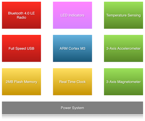
The Nordic Semiconductor nRF8001 is used with a Fractus Micro Reach Xtend Chip Antenna. Communication is done over SPI 1.
The microcontroller has full speed USB support.
The Energy Micro EFM32LG330F256 microcontroller used is based on an ARM Cortex M3 processor. It has 256kB of flash and 32kB of RAM.
A 32kHz crystal is present on the low frequency crystal pins of the microcontroller. This is used by the firmware to provide the real time clock functionality.
The ST LIS3DH 3D accelerometer with digital interface is used. Communication is done over SPI 1.
The Freescale Semiconductor 3D magnetometer MAG3110 with digital interface is used. Communication is done over I2C 1.
There are a number of temperature sensors in the system. The microcontroller, accelerometer, and the magnetometer chips each have temperature sensors.
Three full color RGB LEDs are driven by a Texas Instruments LP5523 LED driver. Communication is done over I2C 1. There are also four LEDs (3 red, 1 green) driven directly via the microcontroller.
The Winbond W25Q16 2MB flash memory is used. Communication is done over SPI 0.
Power is provided to the system via a rechargeable lithium polymer battery. The battery is recharged via USB. Charge status, charge current, and battery voltage can all be monitored via the microcontroller.

The I2C 0 bus is available on a 6-pin header to communicate with an external circuit. Unregulated and regulated power is also available along with an extra digital line that can be used for an interrupt line (or any other purpose).
The I2C 1 bus is used to communicate with the LED driver and the 3-axis magnetometer. This bus can be powered off to save power.
The SPI 0 bus is used to communicate with the Bluetooth 4.0 Low Energy radio and the 3-axis accelerometer.
The SPI 1 bus is used to communicate with the 2MB flash memory. This bus can be powered off to save power.
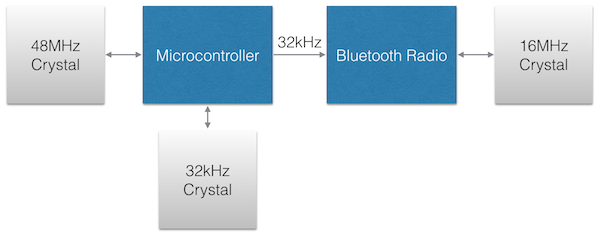
The microcontroller has two crystals: a 48MHz crystal and a 32kHz crystal. The 48MHz crystal is used for USB operation. The 32kHz crystal is used for the real time clock functionality. The 32kHz signal can be passed through to the radio to provide an accurate timing reference. The radio also has a 16MHz crystal used to generate the frequencies used for radio frequency transmission and reception.
The microcontroller Serial Wire Debug (SWD) port is available via test points on the PCB. These test points can be connected to a standard 10-pin Cortex Debug Connector by using a Tag-Connect TC2030-CTX-20-NL cable.
The system can be reset externally by pulling the USB ID pin low for 4 seconds and then releasing it. The USB ID pin can be pulled low by plugging in a USB On-The-Go adapter.